

Views: 0 Author: Site Editor Publish Time: 2026-05-29 Origin: Site
The tractor universal joint drive shaft (PTO drive shaft) is the most critical comp onent connecting the tractor's Power Take-Off (PTO) shaft to the agricultural impleme nt’s input shaft. Correct installation and operation not only prevent equipment failur e but are also essential for guaranteeing operator safety. This guide is compiled in acc ordance with national standards and industrial regulations; all relevant personnel must strictly comply with it.
 Operating Guide for U-joint rive Shaft of Tractor.pdf
GB/T 17126.2-2009 / ISO 5126-2:Agricultural tractors and machinery —Power take-offdriveshaftsandpower-inputconnection—Part2:Specificationsforuseof PTOdriveshafts.
During installation, ensure that the fork joints (the openings of the forks) at both ends of the universal joint shaft are in the same plane. For double-cross universal joint drive shafts, the output shaft will only achieve a uniform rotational speed when the angles between the input and output shafts and the drive shaft are equal, and both fork joints are in the same plane. If the phases are misaligned (e.g., a 90-degree offset), it will cause the output speed to fluctuate erratically, generating severe impact loads and abnormal vibrations, which can easily lead to the breakage of the cross-shaft rollers or the twisting of the shaft tube.
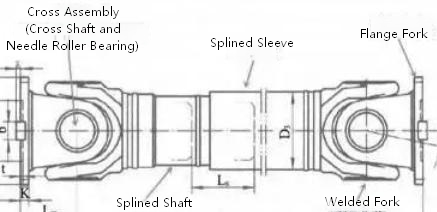
(1) During tillage operations, the angle between the power take-off (PTO) shaft and the drive shaft must be kept at ≤10°; exceeding this limit is strictly prohibited. An excessive angle will result in uneven speed transmission, increasing wear on the universal joint and bearings, and may even lead to transmission resonance or the risk of breakage.
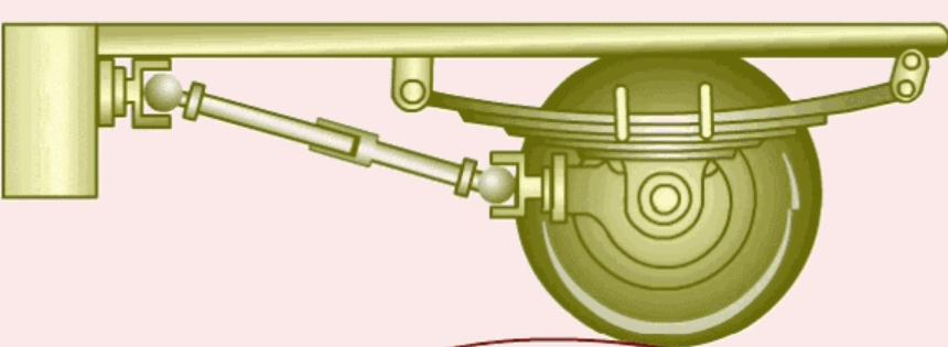
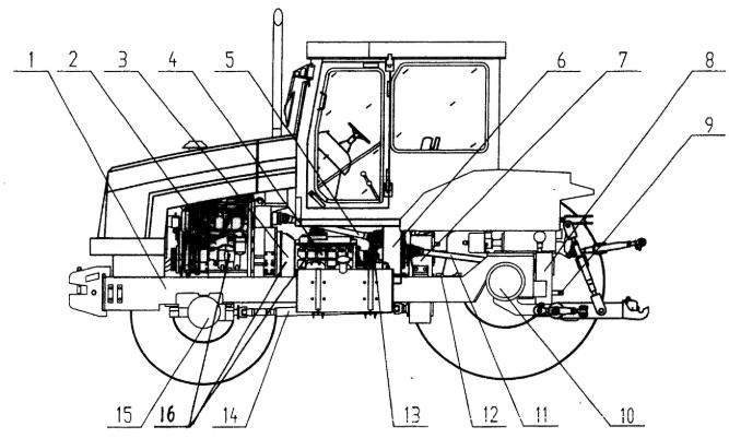
(2) When lifting farm implements to turn at the headland, the angle of elevation must not exceed 25° to 30°. If a greater angle of elevation or long-distance transport is required, the power take-off must be disengaged.
Adjusting the length of the drive shaft is key to preventing it from “jamming” or “coming off.”
(1)When the agricultural implement is lifted to the highest point, an axial sliding cle arance allowance of more than 15mm to 20mm must be retained between the universal jo int drive shaft and the spline sleeve, preventing the drive shaft from "bottoming out" or p ulling out at the extreme position of the suspension system, and avoiding mechanical inte rference that damages the gearbox or the universal joint. If the clearance is too small (<1 5mm), the square shaft can easily be completely pushed into the sleeve tube when the agr icultural implement hits hard ground or experiences bumps, causing the total length of th e drive shaft to exceed the limit and ruining the universal joint or the gearbox input shaft; if it is too large (>20–30mm), it may reduce transmission stability or increase the risk o f pulling out (especially during lowering).
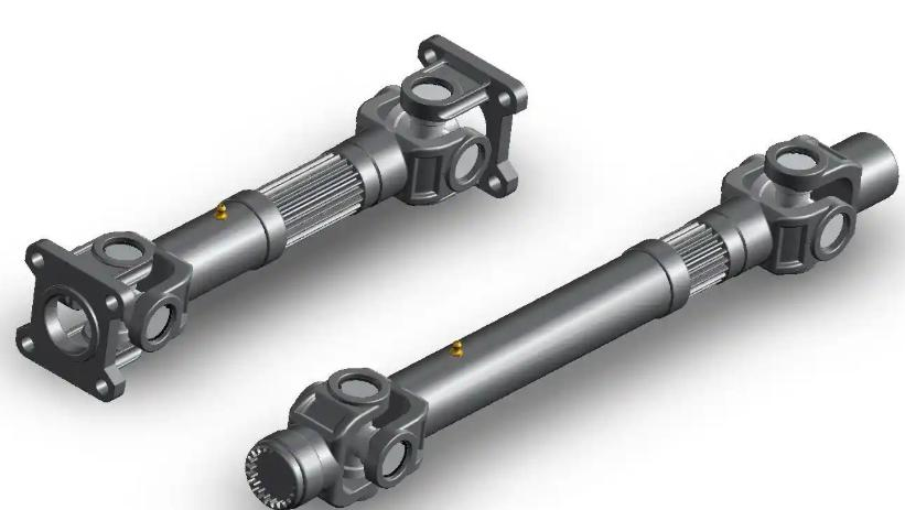
(2) When the agricultural implement is lowered to the lowest (soil-engaging) positi on, the mating length between the tractor PTO drive shaft and the implement spline sho uld be no less than 200mm, and greater than three times the diameter or cross-sectional length of the splined shaft, ensuring that the drive shaft will not pull out under the maxi mum extension working condition.
It is strictly prohibited to suddenly engage power or aggressively slam the throttle when the agricultural implement enters the soil. Power must be engaged first in the lifted state, and after the rotational speed stabilizes, the agricultural implement should be slowly lowered into the soil.
(1)Before engaging power, ensure that the agricultural implement [such as a rot ary tiller, plow, etc.] is in a completely lifted state, the power take-off shaft [PTO] is di sengaged from the clutch, and the throttle is at a low speed.
(2)Engage the power smoothly (by slowly releasing the clutch pedal or moving the PTO lever), and once the engine and implement speeds have stabilized, gradually increase the throttle to the speed required for the task;
(3) Lower the implement into the soil slowly to avoid sudden increases in load that could overload the drivetrain, cause the engine to stall, or damage the equipment ;
(4) It is strictly prohibited to "start after entering the soil" or "aggressively slam the throttle when entering the soil", otherwise it can easily cause universal joint breakage, gearbox damage, engine overload, or even safety accidents;
(5) If stopping or transferring is required during operation, the power must be cut off and the agricultural implement must be lifted first before moving or reversing (reversing or sharp turning is prohibited after entering the soil).
When operating implements such as rotary tillers, the tractor must not make sharp turns or reverse. When turning at the headland, the implement must be raised. If power has not been disconnected, the lifting height must not exceed the universal joint’s safe angle (typically ≤30°), and the engine speed should be reduced.
(1) It is strictly prohibited to make sharp turns or reverse during operation, other wise it can easily twist and break the blade shaft, damage the universal joint, or cause a rollover risk;
(2) When turning at the headland without cutting off power, the rotary tiller must be appropriately lifted first (ensuring that the blades emerge from the soil and the univ ersal joint inclination angle is ≤30°), while simultaneously reducing the throttle and l owering the PTO rotational speed, avoiding transmission system overload;
(3) If the power is cut off before turning or transferring, it can be lifted to the highest position and locked; lifting too high during operation or forcing a turn during high-speed operation will cause breakage due to the universal joint exceeding its limit angle, or cause hydraulic system shock; (4) Before all operations, it must be confirmed that there is no one around; it is strictly prohibited to approach rotating parts when the rotary tiller is running, and the machine must be stopped and the power take-off must be cut off with priority before lifting or adjustment.
(1) Lubrication cycle: Check and lubricate the cross-shaft universal joint and the spline sliding pair every 8–10 hours of operation or before the first use every day; if the working environment is dusty, humid, or under high-intensity operation, the frequency should be increased.
(2) Lubricant type: Extreme pressure lithium-based grease (such as No. 2 or No. 3 ) should be used, avoiding calcium-based grease (poor heat resistance, easy to emulsify); No. 3 is suitable for high temperature/heavy load, and No. 2 is suitable for low temperature/light load.
(3) Key operational points: Use a grease gun to aim at the grease nipple (if any) and inject grease under steady pressure until the old oil and impurities are squeezed out by the new grease from the cross-shaft oil seal gap or the edge of the spline boot, indicating that the cavity is completely filled; if there is no grease nipple, manual coating is required after disassembly, inspection, and cleaning.
(4) Precautions: If the universal joint or the spline feels jammed, rusted, or difficult to inject grease into, it indicates that the interior is already short of oil or has accumulated dust, and it should be disassembled and washed rather than forcing grease injection; excessive grease injection may burst the oil seal, leading to contamination instead.


